

T129 - Platinum Tools VDV MapMaster 2.0 Tester


The Platinum Tools T129 VDV MapMaster 2.0 Tester combines continuity testing, mapping, tone generation and length measurement functions in a single tester. It includes the tester and all the accessories required for voice, data and video testing & mapping in the field. The T129 is perfect for testing all category cables (Cat5e, Cat6, and Cat 3) and coaxial cables (RG6, RG59, and RG59 Mini).
The Platinum Tools T129 VDV MapMaster 2.0 Test Kit Includes:
(1) RJ45 #1 Remote, (1) F (F to F) Adapter, (1) Coax F #1 Remote, (1) Battery, (1) RJ45 to Alligator Cable, and (1) Instruction Sheet
- Includes: (1) T129 VDV MapMaster 2.0 Tester
- Tests CAT-6, Cat-5e, Cat-5, Cat-4, Cat-3 and coax cables
- Tests shielded cables
- Mapping - video and data cables can be connected to their respective remotes at the same time to improve testing efficiency of 'tech' cable (both data & coax cables in one jacket)
- Patch cables may be tested without removing the master remote from storage
- Mapping - optional data and video, custom ID remotes (numbered 1 thru 19) for locating cable runs to wall outlets are available (see accessories)
- Cable test results displayed in wire map format with connector pin numbers
- Displays length reading in feet or meters
- Low battery icon indicator
- Voltage detection warning icon
- LOOP ON - sets up continuous mode which is useful for trouble shooting intermittent problems
- Cable Types: RJ Cable Length: 1000'
- Minimum cable length for split pairs detection: 1.5 feet
- Maximum Coax Cable Length: Cable resistance varies. See website comparison chart.
- Size: 6.4 x 2.8 x 1.4 inches
- Weight: 9.0 oz. (includes battery and remote)
- Operating temperature: 32 to 122 F
- Storage temperature: -4 to 140 F
- Humidity: 10% to 90%, non-condensing
- Battery Life Active: 425 hours, (9V alkaline)
- Part#: T129
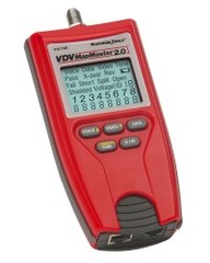
Understanding the T129 VDV MapMaster 2.0 Tester Display
1) Mode: The top line displays the cable type test mode or tone generation mode.
2) Pass/Special Cables: “Pass” will be on if the cable is a properly wired 4-pair T568A/B data cable, a 3-pair one-to-one wired voice cable or a video cable with no faults. In addition, “X-over” illuminates if a properly wired cross-over (uplink) cable is recognized or the “Rev” illuminates if the cable is a properly wired reverse-pinned voice cable. The wire map will show actual pin connections.
3) Cable Faults: The “Fail” icon will be on only if the cable is not wired to one of the cabling standards. An open or short error takes precedence over miss-wires and the appropriate icon(s) illuminates. The “Split” icon illuminates if the designated pairs are not twisted together in the cable, an AC signal fault.
4) Shield: “Shielded” illuminates when a shielded data cable is properly connected at both ends. It will be flashing if there is a short to a wire in the cable along with that pin number and the “Short” indicator.
5) Tester-End Wire Map: The top line displays the pins on the tester end in order. These pins are mapped to the pins on the remote-end shown directly below them on the LCD.
6) Remote-End Wire Map: The bottom line displays the corresponding pin on the remote-end. Dash lines on the remote line indicate short pins. No pin numbers displayed on the remote line are open pairs.
7) Battery Low: The battery low symbol illuminates when the battery is nearing depletion. The symbol will begin to flash when the battery needs to be replaced. Results may be unreliable at this point.
8) Location ID: In the video or the ID modes, the “ID” icon will be on with the number of the remote ID displayed or an error message of “Open” or “Short”.
9) Voltage Detected Warning: If voltage is detected on any of the tester connectors, the “Voltage!” icon is turned on. A check for voltage is performed before each test and if found, no test is run. The tester should be disconnected immediately from the source of the voltage.